F-111 in Detail
Part One - Inlets
by Jim Rotramel
|
|
|
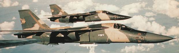
General Dynamics F-111A
A pair of Combat Lancer F-111As are shown with a pair of under-fuselage
AN/ALQ-87 ECM pods and weapon bay M61 gun installation. Note that there
was only a UHF antenna under the nose and the unusual shape of the
outboard weapon pylon. |

HyperScale is proudly supported by Squadron
My fellow modelers have often expressed amazement that while I
have over 1,000 hours flying F-111s, I don’t have a model of one (other than
company models). I probably should have built the Hasagawa 1/72 scale kits,
which are pretty good (except for the Pave Tack pod).
But the focus of this series of articles is the 1/48 scale
Minicraft kit. While it captured the external shape of the aircraft, it has many
faults. I’m going to show the real jet through a modeler’s eyes.
I’ll address the existing aftermarket kits that I’ve seen and
give you an honest appraisal of what I think about them. Unfortunately, to do a
really accurate kit is going to cost you about four to five times the cost of
the kit in resin. One can only hope that maybe Trumpeter will attack this
subject at some point.
IMPORTANT!!
If
you are like me, you like to look at the photos and skip the text. However, there
are a lot of important tidbits in the text of these articles!
Inlets
By FAR, the worst error in the Minicraft kit was the engine
inlets. Neither inlet style depicted by the kit even remotely captured the feel
of the actual articles.
Operational F/EF-111As, F/RF-111Cs, the first FB-111A (67-0159),
and the canceled F-111Ks were fitted with Triple Plow I inlets, which featured
hydraulically translated cowls.
The remaining FB-111A/F-111Gs, as well as all F-111D/E/Fs were
fitted with Triple Plow II inlets, which featured three ‘blow-in’ doors. This
redesign increased the separation between the inlets and fuselage, removed the
external splitter panel, and featured inlet spikes 18-inches longer than the
Triple Plow I’s. The fuselage of Triple Plow II aircraft angled back ever so
slightly at the inlets to create more room between the two structures. These
aircraft also featured a small, round inlet between the engine inlet and the
fuselage. Finally, the F-111D/E/F and FB-111A all had a pattern of gray, and/or
fiberglass-brown panels of radar adsorbing material (RAM)
on the interior of their inlets.
A couple of “special cases”: The second FB-111A (67-0160) was
fitted with Super Plow inlets, which were similar to the Triple Plow II except
that the translating cowls were replaced with two ‘blow-in’ doors instead of
three. The first five F-111Bs (151xxx) were fitted with essentially Triple Plow
I inlets, while the last two (152xxx) had essentially Super Plows. Refer to the
Ginter Book on this subject for details.
While the Triple Plow II inlet reportedly increased inlet area
by ten percent, it’s unclear if that was precisely true. Measurements of the
inlets suggest the TP II may be marginally larger than the TP I, but
nothing like ten percent. However, the frontal area of the inlets may have
increased by that much because of the shifting of the inlet farther out from the
fuselage.
Prior to engine start, the TP II blow-in doors (or TP I movable
cowl) were closed, opening as the engines powered up and sucked open the blow-in
doors (or the cowls opened). They remained open until after takeoff, when
sufficient air could be provided by the intakes alone. After landing they again
opened to increase the air available to the engines during ground operations.
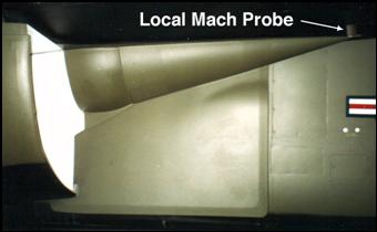 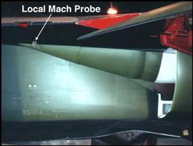
Triple Plow I inlets (left) were most easily distinguished
by the large splitter panel. Note how the inlet spike barely reached the local
Mach probe. Triple Plow II inlets (right) eliminated the splitter panel and the
inlet spike was 18 inches longer than on the earlier inlet, extending well past
the local Mach probe.
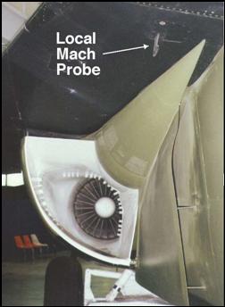 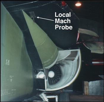
This view of the TP I inlet on the left clearly shows the
warped shape of the splitter panel and the lack of inlet RAM. Note how far
inboard of the local Mach probe the spike is. The TP II inlet on the right shows
how far outboard the inlet was shifted (note how close the it is to the local
Mach probe), the length of the inlet spike, and the inlet RAM.
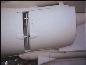 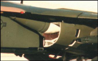
The TP I translating cowl (left) and the triple blow in
doors of the TP II inlet (right).
Note: No aftermarket correction sets have been produced to correct
this serious error, although Scaledown has it on their list of things to do. In
addition, they’ve promised seamless intakes at some point as well.
Text Copyright © 2002
Jim Rotramel
Images Copyright © 2002 United States
Department of Defense and Jim Rotramel
Page Created 07 March, 2002
Last Updated
15 December, 2003
Back to Reference Library
|
 Home |
What's New |
Features |
Gallery |
Reviews |
Reference |
Forum |
Search
Home |
What's New |
Features |
Gallery |
Reviews |
Reference |
Forum |
Search