F-111 in Detail
Part Three - Wings
|
|
|
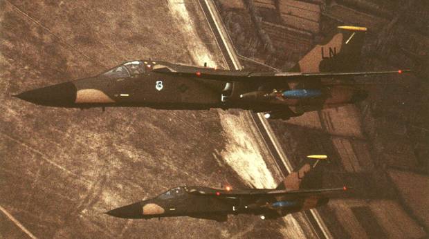
A pair 493rd TFS F-111Fs from the 48th TFW
orbiting near Konya Bombing Range in south-central Turkey in February
1986, two months before Operation El Dorado Canyon. Note the difference in
profile when the Pave Tack pod was retracted (foreground) and extended
(background). Also, note that the AN/ALQ-131 ECM pods at this time had
white radomes. Each aircraft was armed with GBU-10E/Bs (with blue, inert
warheads) on the outboard pylons and SUU-21/A practice bomb dispensers in
the inboard pylons. |
by Jim Rotramel

HyperScale is proudly supported by Squadron
F-111 wings had full-span slats and double-slotted flaps. The
trailing edge of the flaps had a curious ‘bump’ on all variants of the aircraft.
They swept back into the top of the fuselage and were covered by large panels
called ‘over-wing fairings’. These fairings were hinged at the front to lift up
during supersonic or high-G flight and equalize air pressure within the
fuselage/wing cavity.
Roll control was provided by two sets of spoilers. The inboard
set ‘locked down’ when the wings swept past 45 degrees, while the outboards
locked down at 47 degrees.
The FB-111A, F-111B and F-111C featured wingspans extended by
seven feet.
When parked, the F-111’s wings were usually either swept back to
54 degrees or forward to 16 degrees with the flaps at 35 degrees and slats
extended (the stabilizers ‘drooped’ until supplied with hydraulic pressure
during engine start). NOTE: you DON’T have to buy aftermarket flaps and
slats—it’s perfectly acceptable to build a parked aircraft with the flaps and
slats retracted.
After engine start, the wings were set to 16 degrees during the
ground checks, and normally to 54 degrees for taxi. Prior to takeoff they were
again put to 16 degrees with the slats down and the flaps at 25 degrees. At this
time the ‘ground roll spoiler’ switch was activated, raising the spoilers
whenever both throttles were in idle. This feature killed lift and shortened the
ground roll during landings or takeoff aborts.
Takeoff was at about 160 KTAS, and the wings were quickly
‘cleaned up’ and swept to 26 degrees for climb out, initial cruise, and/or air
refueling. The most common sweep settings for low level were 35 or 44 degrees,
with the latter being used for ‘toss’ weapon deliveries.
Depending on the amount of fuel remaining, landing approaches
were normally flown at slightly slower speeds than takeoff, with the sweep set
at 16-20 degrees, slats down and flaps at 35 degrees (25 degrees if single
engine). After landing, the ground roll spoiler switch was deactivated and the
wings swept to 54 degrees for taxi back to parking.
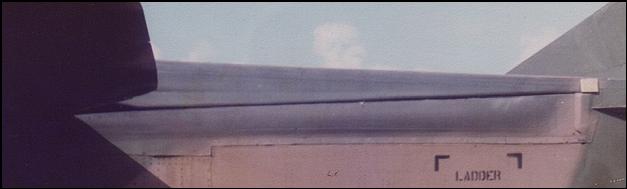
The fabric wing seal that covered the wing cavity is shown
above.
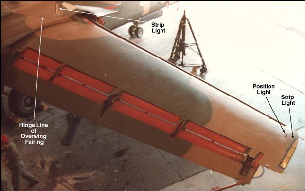
The top of an F-111D wing with the flaps and slats fully
deployed.
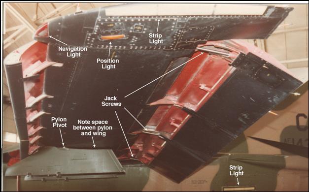
The bottom of an F-111D wing the flaps and slats fully
deployed. Note that while the pylons are flush with the wing in front of the
pivot point, there is a gap between the two aft of that.
Scaledown has
produced wings with flaps and slats extended for both short and long wings. The
wings are complete units, including precut wings that allow you to throw away
the kit wings. Because of resin shrinkage, the fit of the flaps and slats isn’t
perfect, but shouldn’t pose a problem for a reasonably capable modeler. One note
on the short wings—fill the hole for the outboard pylon. Short-wing airplanes
never used that pylon.
Paragon has
produced a modification kit for the short wing airplanes for extended flaps and
slats as well. These are a bit more of a modeling challenge because they require
you to cut away the front and back of the kit wings. Shrinkage is a minor
problem with these wings as well, but a good model can be made using this kit as
well. One nice touch with the Paragon kit is the inclusion of photo-etch parts
to simulate the fabric wing cavity seals.
Wing Stations
All F-111s were constructed with provisions for four outboard
pylons fixed for carriage at 26 degrees of wing-sweep. However, of these, only
the inboard fixed pylons were used operationally, and only by FB-111As for
carriage of two extra 600-gal external fuel tanks (explaining the ‘pigeon-toed’
appearance of some FB-111A fuel tanks on takeoff).
Other variants only used the four movable inboard pylons, with
external tank carriage being limited to F-111Cs, F-111Es, and F-111Fs (and ONLY
from the outboard pylon). Operationally, fuel tanks would probably only be used
in conjunction with AGM-69A SRAMs (FB-111As only) or B61 nuclear weapons on the
inboard pylons.
The
“600-gallon” external fuel tanks in the Minicraft F-111 kits were woefully
undersized. The Monogram A-10 tanks were closer, but still undersized. Scaledown
has produced corrected fuel tanks, with different versions for both the tactical
and strategic aircraft.
As training aircraft FB-111As modified as F-111Gs no longer
carried any tanks. However, they did retain the FB-111A pylons, which were
pointed at the front and more sharply angled at the back than those found on
other F-111s.
Scaledown has
produced the FB-111A/F111G pylons.
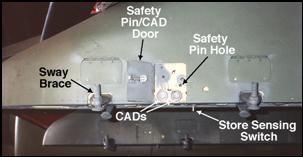 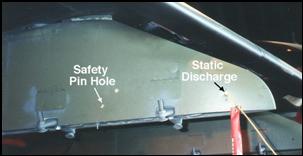
When stores were loaded on the wing pylons, safety pins
were inserted in the pylons to prevent them from being inadvertently jettisoned.
These pins were always inserted from the outboard side. That meant that on the
left wing only, the small door that allowed access to the cartridge actuating
devices (CAD) had to be opened whenever the pins were inserted.
F-111C Notes
Australian bought 18 F-111C aircraft with the extended wing tips
and strengthened landing gear of the FB-111A design (although its avionics
remained virtually identical to those in the F-111A). Initial delivery occurred
in July 1968. Four F-111Cs were modified to RF-111C standard in 1979-80 by
installing a pallet in the weapons bay and a control panel in the cockpit
(A8-126, 134, 143, and 146).
During 1983, F-111C A8-147 was modified with the same Pave Tack
system used by the F-111F. All other F-111Cs were modified in Australia
beginning in March 1985. At about the same time, they received other
modifications to make them compatible with the GBU-15 glide bomb, but without
the AN/AXQ-14 data link pod. Three final weapons which were unique to the F-111C
community were the indigenous Karinga cluster bomb, AGM-84 Harpoon, and AGM-88
HARM.
The F-111C fleet received the avionics update program (AUP)
in the early 1990s. This resulted in a cockpit configuration similar to Pacer
Strike F-111F.
F-111E Notes
Only 25 F-111Es received the extensive Avionics
Modernization Program (AMP) changes during
1990-92. They were 68-0022, 0027, 0032, 0040/41, 0044, 0047/48, 0050, 0054,
0063, 0067/68, 0071/77, 0079/80, 0082/84). These aircraft replaced F-111Gs at
the 428th FS in July 1993, but were retired soon thereafter.
F-111F Notes
During the early 1980s all F-111Fs were modified with the
Pave Tack system which enabled the WSO to visually acquire targets 24-hours a
day using high-quality infrared video, and self-designating them with a laser
for attack with laser guided bombs (LGB).
Integration of this system required additional cockpit controls and displays,
the most significant of which was the virtual image display (VID).
Starting in 1993, 21 F-111Fs were upgraded by Rockwell’s
Pacer Strike program to make them very similar to the AMP F-111Es. They
were: 70-2399, -2405, -2411; 71-0883, -0884, -0886, -0887, -0888, -0889, -0890,
-0891, -0893; 72-1442, -1443, -1444, -1446; 73-0710; 74-0178, -0180, -0184,
-0185, -0186. All were initially assigned to the 524th FS, with some later being
transferred to the 523rd FS. 72-1444 was originally at Eglin AFB and went
directly to the 523rd.
Paint Scheme Notes
F-111As had a different camouflage pattern than all the other
tactical variants. This is most evident around the nose. They initially had
white undersides, but this was changed to olive drab on the Harvest Reaper
F-111As. By the time of the Constant Guard V deployment to Thailand in 1972 the
undersides were black, a color used until the overall gray scheme was adopted by
tactical F-111s in the early 1990s. F-111s were the last aircraft to use the
Vietnam era colors, with Desert Storm aircraft using this scheme because most
aircrew found it much easier to fly tactical formation with.
US-based F-111A and F-111Ds had hard-edged patterns, virtually
identical between aircraft, while European-based F-111Es and F-111Fs had soft
edged patterns, which were generally similar from one aircraft to the next.
FB-111As were painted in a unique scheme using SAC colors.
Aircraft 68-0250 was painted in a new ‘European One’ scheme in early May 1984,
with all other FB-111As being repainted in due course.
Libya Raid Aircraft: When the Libya raid occurred, the
tail codes and national insignia were flat black. Some aircraft carried color
wing and squadron insignia (the former on the left, the latter on the right).
The last three digits of the tail number were stenciled in white on the
front-bottom corner of both nose wheel doors. Pilot and crew chief names were
painted in white on the left nose gear door, while the WSO and assistant crew
chief names were on the right. No AIM-9s were carried. Within a couple of months
of the raid, a hand-painted rendition of the World War II North African Campaign
ribbon began to appear on all 48th TFW aircraft (these were carried until the
aircraft transferred to Cannon AFB after the Gulf War). None of the raid
aircraft received any special markings except for 70-2390, which eventually was
adorned for a short period with a small (about eight-inch long) vertical white
bomb, shaped very much like a Fat Man atomic bomb. It was located on the left
side of the fuselage just in front of and slightly below the bottom front corner
of the escape capsule.
Desert Storm Aircraft: The 493 TFS reversed black and
yellow on its squadron patch after Desert Storm, and its fin cap became black
with yellow stripes. All F-111Fs based at Lakenheath were inflicted with an
incorrectly proportioned national insignia from the late 1980s, many until they
transferred to Cannon AFB. Applied with a stencil that made the ‘bars’ about
half again as long as they should be, these solid-pattern insignia were applied
to many aircraft during the Gulf War. A correctly proportioned F-15E type
broken-pattern stencil insignia started being used on the F-111Fs at Lakenheath
at about the time that the F-15Es started arriving there.
Gray Scheme: Starting in 1990 the depot in Sacramento,
where all stateside-based F-111s were overhauled, had to stop painting aircraft
because of environmental concerns. At about the same time a decision was made to
change to a different type of paint stripping process and paint. The new paint
was the same 36118 Gunship Gray used on F-15Es. F-111Ds and F-111Gs were painted
at the rate of about one per week at Cannon AFB, where the priority became
painting over the former FB-111As’ SAC colors as quickly possible. After the
first few airplanes were painted, it was discovered that the accumulation of oil
on the belly beneath the engine bays interfered with paint adhesion enough that
the area between the ventral strakes was left the old color on many aircraft. As
the gray color scheme was applied, the squadron colors were again applied as
stripes on the upper fin. The new scheme wasn’t at all popular with European
aircrew, with the few aircraft that were painted that way being quickly
repainted. Only the first AMP F-111E saw combat in gray paint; aircraft 68-0050
flew a single combat sortie on 25 February. (Although FB-111A 68-0294 and F-111G
67-7194 had experimental radomes of 36081 gray fitted beginning about 1990, the
black radomes remain standard.)
F-111Cs used Vietnam-era colors and F-111D/E/F patterns until
being painted gray beginning at about the same time as the AUP modifications
were made.
EF-111As had a unique gray color scheme, and had never carried
squadron colors.
Text Copyright © 2002
Jim Rotramel
Images Copyright © 2002 United States
Department of Defense and Jim Rotramel
Page Created 08 March, 2002
Last Updated
15 December, 2003
Back to Reference Library
|
 Home |
What's New |
Features |
Gallery |
Reviews |
Reference |
Forum |
Search
Home |
What's New |
Features |
Gallery |
Reviews |
Reference |
Forum |
Search