The Aircraft in question is NASA 843, flown at Nasa's Dryden Flight Research
Center which is located at Edwards AFB in California. Nasa 843 is Navy Buno
161519, which is F/A-18A-6-MC, Serial no. 36, a Lot 4 acft. Nasa 843 is also a
former Blue Angels bird, as is most of the Dryden fleet of F-18's with a few
exceptions.
 |
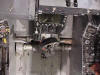
This view is of the aft cockpit
bulkhead showing the seat rails installed and the aft bulkhead equipment.
On the left side of the cockpit bulkhead (right side on your screen) is
the Oxygen Heat Exchanger and plumbing, the Communications assy and the
seat electrical (connected to the seat rail). On the right side of the
cockpit (left on your screen) is the JAU-29 Initiator, SMDC line and the
gas hose that connects to the Ballistic Quick Disconnect (QD).
Some of you may not realize, but
the seat bucket is removable from the rails to assist in the removal of
the seat from the cockpit. Its held on by 4 nuts. And this is the only
portion that raises and lowers, the rails don’t move.
|
 |
Close up of the right side of the
bulkhead. Visible are the JAU-29 init, gas hose and the .3 second Time
Delay initiator mounted on the seat rail (yellow assy). The green oxygen
hose is a NASA mod. We added an Air Force style Panel Mounted Oxygen
Regulator and kept the Navy system as a back up, and the kit Emergency 02
as a tertiary system. Yes, triple redundancy.
|
 |
Close up of the TRM trip rod
connection to the bulkhead (yellow tube & chain) also shows the
ballistic qd location.
The box in the upper left portion
is the Fan Test Box. This is the upper right side of the aft bulkhead.
|
 |
Another shot of the left side of
the aft bulkhead. The brown area on the console is the personal services
disconnect and includes the oxygen connection from the acft to survival
kit (aft), Vent suit system (middle) and Anti-G suit (fwd).
|
 |
Another shot of the aft bulkhead,
right hand side.
|
 |
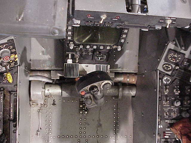
Details of the control column
(stick), Lower Inst. Panel and the forward section of the floor. Right in
front of the stick, the floor is raised 3 inches. The black fitting behind
the stick is the floor attach point for the leg restraint lines.
|
 |
Left Rudder pedal
|
 |
Right Rudder pedal
|
 |
Instrument panel
|
 |
Left console fwd showing the
blending into the inst panel. The long yellow handle is the manual Canopy
Jettison Handle and safety pin/flag.
|
 |
Canopy Motor (open/close) from the left side. This is also the upper
catapult attach point. NOTE the seat is not attached to the acft, only
the catapult is. The seat is attached to the catapult by means of the Top
Latch Mechanism.
|
 |
Canopy motor from the right side.
|
 |
Aft canopy deck.
|
 |
Left Canopy Jettison Rocket Motor,
SMDC Line and canopy Defog bellows.
|
 |
Right canopy Jettison Rocket
Motor.
|
 |
Equipment Bay, left bulkhead. Nose
of acft is to your right.
|
 |
The aft bulkhead of the equipment
bay.
|
 |
Right bulkhead of equipment bay.
Nose of acft is to your left. Missing from the rack is some piece of
war-fighting gear NASA doesn’t use.
|
 |
Forward bulkhead of equipment bay.
This shot shows the right hand side of that bulkhead.
|
 |
Fwd bulkhead of equipment bay.
This shot shows the left side.
|
 |
Looking straight down at the cover
over the equipment bay and the canopy motor. This shield is in really good
shape, generally these are trashed, or the velcro strips are worn, or the
snaps are shot, etc.
|
 |
Upper Moveable Canopy Deck showing
the Canopy Unlatch Thruster and associated SMDC lines and initiators. This
area that the rod attaches to will separate and the canopy will go flying
off where ever it wants on ejection. The initiators follow SMDC lines to
the Canopy Jettison Rocket motors showed elsewhere. This view is from the
left side looking under the glass.
|
 |
Same View as –146s but from the
right side.
|
 |
Looking through the canopy from
behind showing the equipment bay, back of seat, canopy motor.
|
 |
Looking straight down on the
stick. Shows where the floor should raise.
|
 |
Same shot, slightly aft from above.
|
 Home |
What's New |
Features |
Gallery |
Reviews |
Reference |
Forum |
Search
Home |
What's New |
Features |
Gallery |
Reviews |
Reference |
Forum |
Search