|
Building a Royal Australian Air Force
F/A-18 Hornet
by Paul Gillan

HyperScale is proudly supported by Squadron
The Royal Australian Air Force purchased 75 McDonnell Douglas F/A-18A and B model aircraft in 1982 to replace its aging fleet of Dassault Mirage IIIO aircraft. The fleet was to consist of 57 AF/A-18A single seat fighter and 18 AF/A-18B (initial designation was ATF-18A) trainer aircraft.
The first two aircraft (A21-101 & -102) were flown in a marathon 15 hour flight from NAS Lemoore California USA to RAAF Base Williamtown New South Wales Australia on 17 May 1985.
Serial numbers in RAAF service are A21-001 through A21-057 for all single seat aircraft and A21-101 through A21-118 for duals. Aircraft are Block 14 through Block 23 aircraft. To date, four airframes have been lost (A21-104 / -106 / -041 & -042) with the loss of four aircrew and a DSTO scientist.
Early in the RAAF Hornet life major reworks were undertaken by McAIR to strengthen the aircraft engine mounts, add the distinctive LEX fence, add cleats to the inboard side of the Vertical Tails (VT) and to modify and stiffen the VT spars by adding a composite butterfly patch, reworking fastener holes and adding a odd knife shaped doubler to the LH side of the VT. In recent years, RAAF Hornets have undergone a range of upgrades which have resulted in a number of significant external changes.
RAAF Hornets were painted in FS 35237 (top deck) and FS 36375 (lower deck) with hi-visibility markings.
National markings - Roundels (FS 15050 Blue / FS 17925 White / FS 11136 Red) were featured on the nose barrel and lower wing surfaces. A tricolour rhomboid (red forward) was on the upper VT. All other markings were counter shaded in the opposing colour.
Changes to the scheme starting in about 2000 were to make all national insignia low-vis and to replace the rhomboid with an Australian Flag. Later, the flag became low viz also.
Three 77SQN aircraft have carried experimental schemes:
A21-001 - featured a scheme where the upper deck received an FS 36118 rather than FS 35237. Markings were low visibility.
A21-007 - carried an overall FS 36118 finish with high viz markings and stencilling in FS 36375.
A21-020 - carried an overall FS 36118 finish with high viz markings and stencilling in FS 37038 Black.
Wheel wells, avionics and engine bays are finished in FS 17925 White. Main Landing Gear (MLG) and Nose Landing Gear (NLG) doors are edged in FS 11136 Red. The speed brake and speed brake well are finished in the upper deck colour.
The Gun Holdback Indicator on the Gun Access Door and the Gun Elec Safety Switch are finished FS 13797.
The Chaff & Flare Safety Indicator, in the top aft corner of the panel just forward of the first LH side avionics cheek bay door, is finished in Day-Glo Sunburst Yellow, no FS equivalent.
The cockpit is finished as follows:
Location |
Colour |
Above the canopy sill |
FS 37038 Black |
Below the canopy sill |
FS 36231 Grey |
Controls |
FS 36440 Grey |
Emergency Controls |
FS 37038 Black and FS 13538 Orange-Yellow
[diagonally striped top RH to bottom LH] |
Chaff Flare Switch & Emergency Jettison |
FS 11136 Red |
Seat |
FS 37038 Black |
Major External Identifiers
Before 1988
No LEX Fence,
No NLG launch bar or associated kit,
No carrier landing light box on NLG
Additional landing light fitted to NLG.
Cleats fitted to all VT during production.
After 1988 to 1999
Lex fence standard.
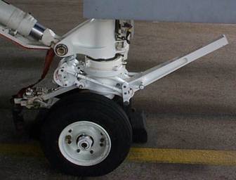
NLG had either no launch bar or a ballast weight fitted.
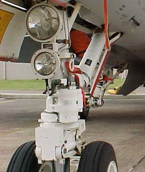
Beyond 2000
New NLG Dummy Launch Bar fitted.
HUG 2.1 installs 5 CIT antenna to nose, changes two antenna to swept type, adds GPS bump to dorsal deck aft of swept antenna.
Ordnance Loads
Stations are numbered 1 through 9 from left to right looking from the tail forward.
1 |
2 |
3 |
4 |
5 |
6 |
7 |
8 |
9 |
Wing tip |
Under Wing |
Under Wing |
LH Intake |
Centreline |
RH intake |
Under Wing |
Under Wing |
Wing tip |
Peace Time - Usually seen with Captive AIM-9 on either wing tip launcher and two external tanks on STN 3 & STN 7. FLIR pod fitted at STN 4 as required.
Over Diego Garcia - AIM 9 on each wingtip (STN 1 & 9), three tanks (STN 3 / 5 / 7), 2 x AIM 120 on STN 2 & 8, FLIR on STN 4 and AIM120 on STN 6.
Over Iraq – AIM 9 on each wingtip (STN 1 & 9), three tanks (STN 3 / 5 / 7), GBU-12 on STN 2 & 8, FLIR on STN 4 and AIM120 on STN 6. This load may have varied with targeting.
Using a 1/48 Hasegawa ‘C’ model to represent a RAAF ‘A’ model.
Build the kit per the instructions with the following exceptions.
Step 1: The seat fitted to RAAF Hornets are SJU-9/10. The only difference to these seats is not an issue to the modeller. Either detail the kit seat or replace with a resin seat.
Step 3: Holes for LEX fence and pylons as required.
Step 5: Fill the small square panel aft and above the LH & RH AOA probes if building aircraft A21-012 and above or A21-108 and above. All earlier aircraft have this panel with the corresponding ‘RESCUE’ arrow. Do not use the Rescue or panel decal for other aircraft.
Step 8: Build NLG according to era with or without launch bar and other equipment.
Step 10: K27- this type of AOA probe changed to a cone type in the mid-life of the Hornet. For post Hug 2.1, change K26 to swept type antenna. Sand antenna bump off RH NLG Door.
Step 13: Use K11 burner cans
Step 14: Fill square recess on G4. Do not punch forward holes.
Step 15: Vertical tails are built as LH as they are, allegedly, interchangeable. On the RH side of the VT, fill the door at the lower aft corner. Add butterfly patch to both sides and Knife Fitting to LH sides only. Remove the middle fairing at the top of the tail (for ‘C’ model tail only).
Step 16: Have fun polishing out that canopy seam……
Step 20: Don’t use B21.
Step 21: Don’t use K24 or K2. For post HUG 2.1, add CIT antenna (use ‘T’ shaped extrusion with base 0.044” and vertical leg 0.023”. Cut to 0.195” long. Step cut forward and aft edges on vertical 0.015” back and at an angle of about 10 degrees. The vertical leg is to be triangular in cross section with the base being 0.014” and the top 0.003”. Bottom leg to be 0.015” each side. End s of horizontal leg to be rounded off) and GPS bump.
Also, add stiffener above forward engine bay door. Strip light will require removal and replacement.
Recommended further reading:
PHANTOM, SKYHAWK & PHANTOM IN AUSTRALIAN SERVICE
Stewart Wilson
Aerospace Publication
ISBN 1 875671 03X
HORNETS DOWN UNDER
Andrew McLaughlin
Phantom Media ISBN 0 646 44398 4
NLG WITH Dummy Launch Bar Fittted
Original NLG Configuration with Ballast fitted
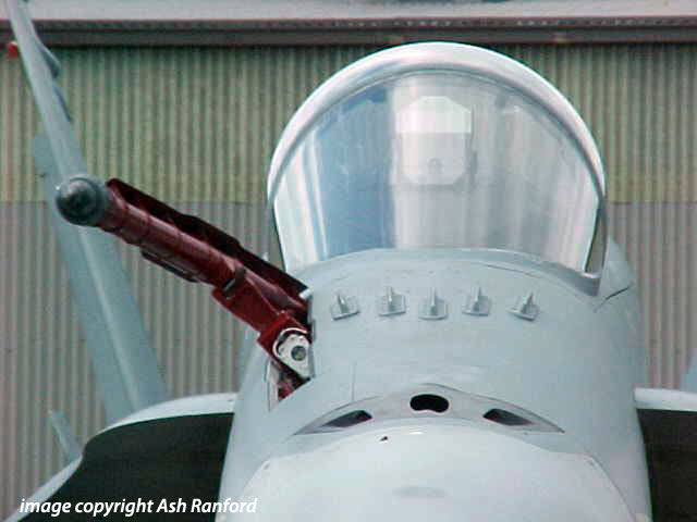
POST HUG 2.1 CIT antenna fit
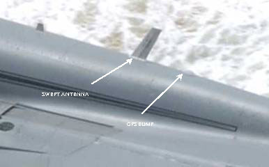
POST HUG 2.1 Swept antenna and GPS bump fit
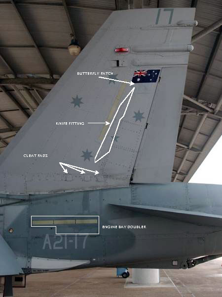
Vertical Tail Outboard
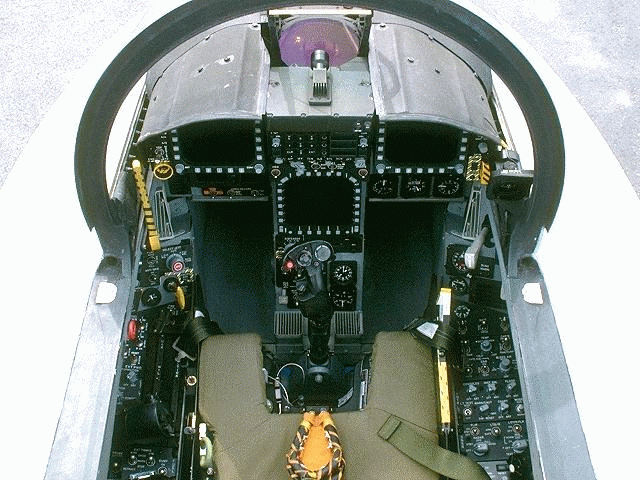
Cockpit
(REPRESENTATIVE – NOT RAAF IMAGE – COPYRIGHT UNKNOWN)
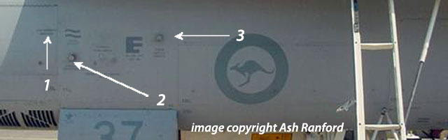
FORWARD FUSELAGE SAFETIES
1. Gun Holdback indicator
2. Gun Elec Safety Switch
3. Chaff & Flare Safety Switch
Text & Images Copyright © 2008 by Paul Gillan except where noted
Page Created 29 September. 2008
Last Updated
29 September, 2008
Back to Reference Library |
 Home |
What's New |
Features |
Gallery |
Reviews |
Reference |
Forum |
Search
Home |
What's New |
Features |
Gallery |
Reviews |
Reference |
Forum |
Search