Archival Show and Tell #3
P-38 Droop Snoot
by Dana Bell
|
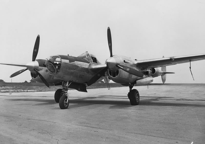
A 3/4 front ground view of P-38L 43-56295 after completion of Droop Snoot modifications. A second aircraft featured in the newly found images was listed as 43-56281. |

HyperScale is proudly supported by Squadron
Several years ago, there was a request on HyperScale for good photos of the interior of the P-38 Droop Snoot modification. As I recall, there weren’t many good shots to be found, but last week I tripped across the enclosed images while reviewing an armament file in the Sarah Clark Collection, US National Archives Record Group 342. The materials weren’t indexed as “Droop Snoots,” which helps explain why they took so long to turn up.
There were no written reports attached, and the short captions gave very few details. All the images were taken on 24 August 1945 (which makes this a late modification) at the Consolidated Vultee Nashville Division. There is no indication whether these photos represent a standard modification or a unique variation, if the mod originated at Nashville, or if it used one of the Droop Snoot kits developed by the Army Air Forces. Still, with any luck the photos will prove helpful for someone trying to complete that Revell, Monogram, Minicraft, or Dragon kit.
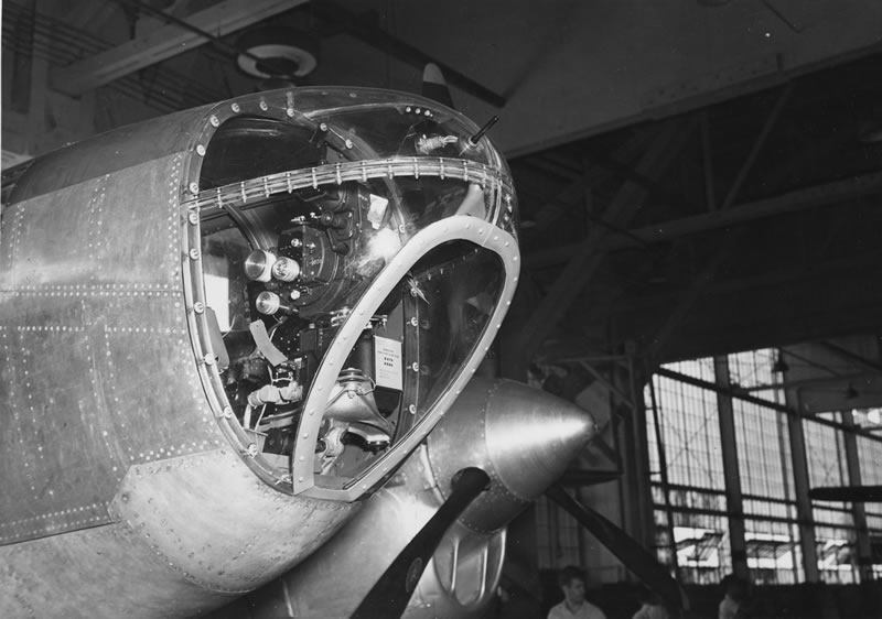
The Droop Snoot modification replaced the P-38's gun nose with a new windscreen, bombsight, and crew position for a bombardier. The bombardier was to act as “master bomber” for a formation of standard, bomb-armed Lightnings.
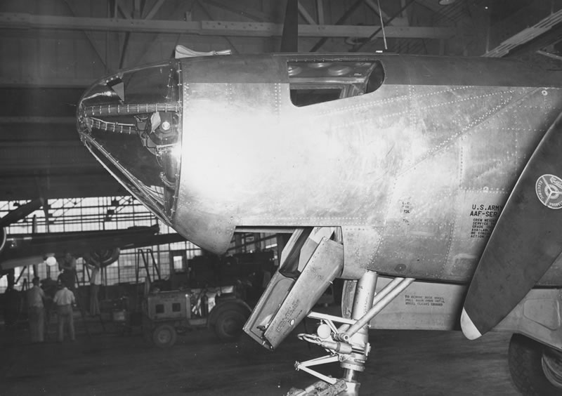
Normal access to the nose compartment was through a ventral hatch, which was also designed to serve as an emergency escape chute for the bombardier. In theory, the bombardier would have enough clearance to safely drop between the props, but movement to either side could prove fatal.
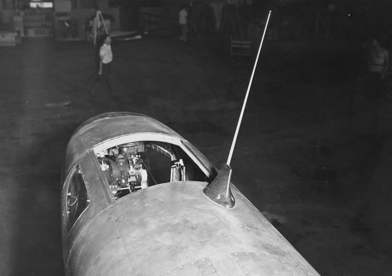
In the event of a belly landing, the bombardier was to escape through a dorsal ditching hatch. The AN-159 radio antenna was mounted just aft of the hatch.
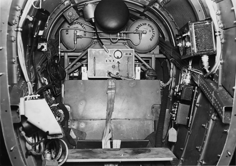
The bombardier’s seat was functional, if not comfortable. Oxygen bottles and the ARW-9 modulator/transmitter were loacted directly behind his head.
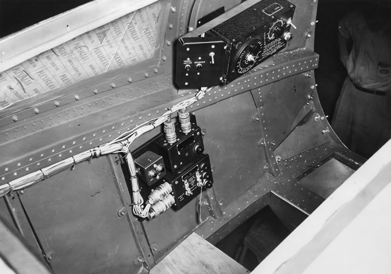
Forward of the left side window, an intervalometer paced the dropping of underwing bombs - a short interval gave a tight bomb pattern, while a longer interval covered a larger footprint. The switches for the ARW-9 and ARW-10 were placed below and aft of the intervalometer.
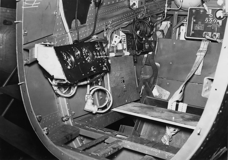
The bombardier’s master panel was at the right side of his cabin. Farther aft is the breathing oxygen regulator and panel. The photos suggest that the cabin interior was finished with Interior Green.
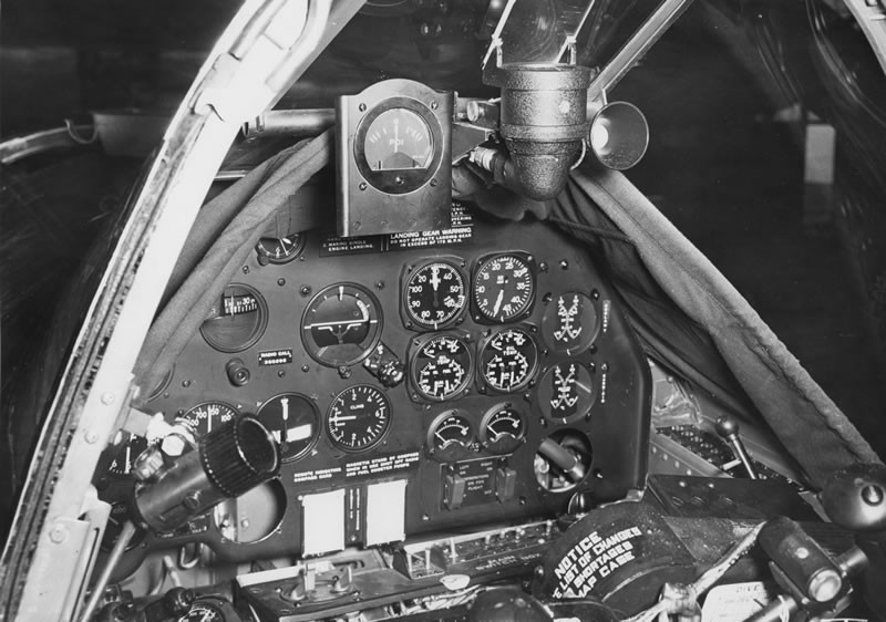
The pilot’s cockpit saw few changes, but a new Pilot Direction Indicator was mounted to the left of the gunsight.
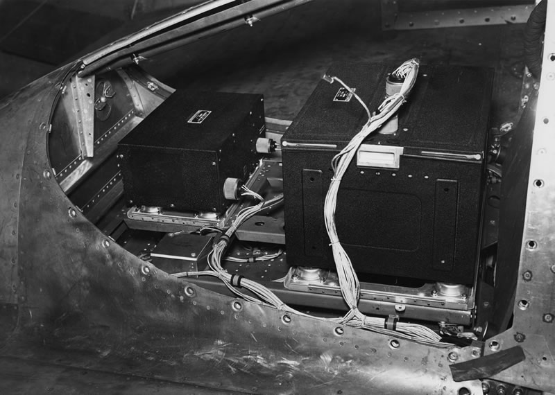
One image showed the original SCR-522 command radio installation, while a second photo...
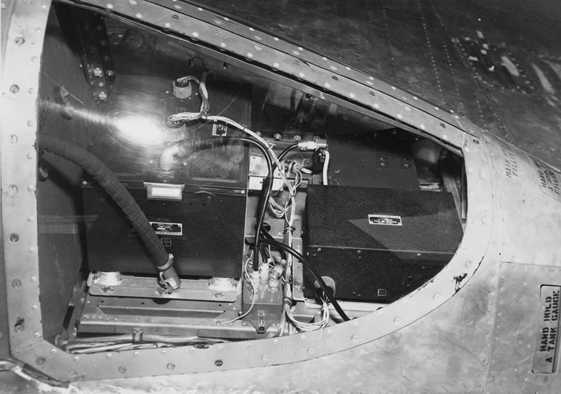
gave a comparison with the new ARW-10A radio installation
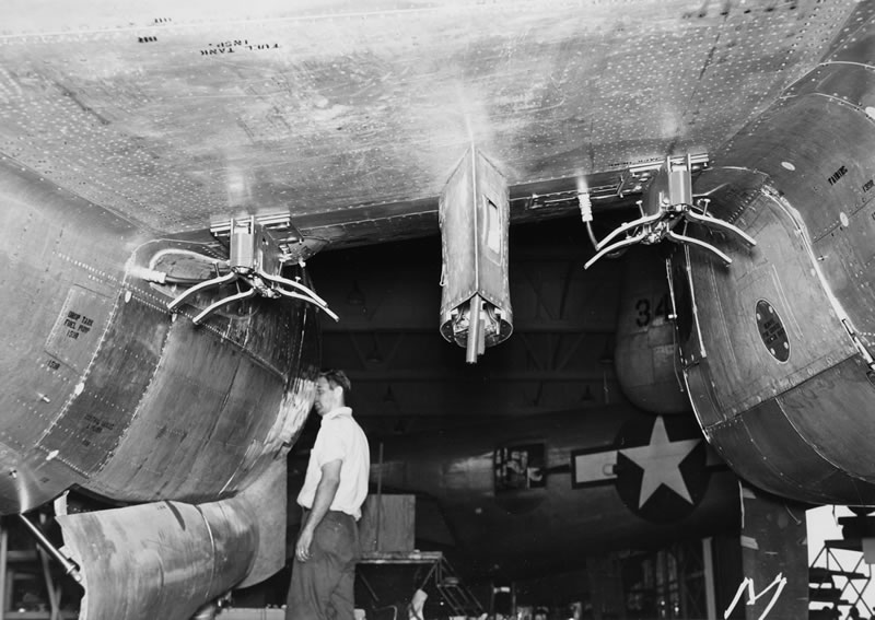
An S-1 bomb rack was added to either side of the drop tank rack, with a maximum load of 4 x 1,000 pound bombs
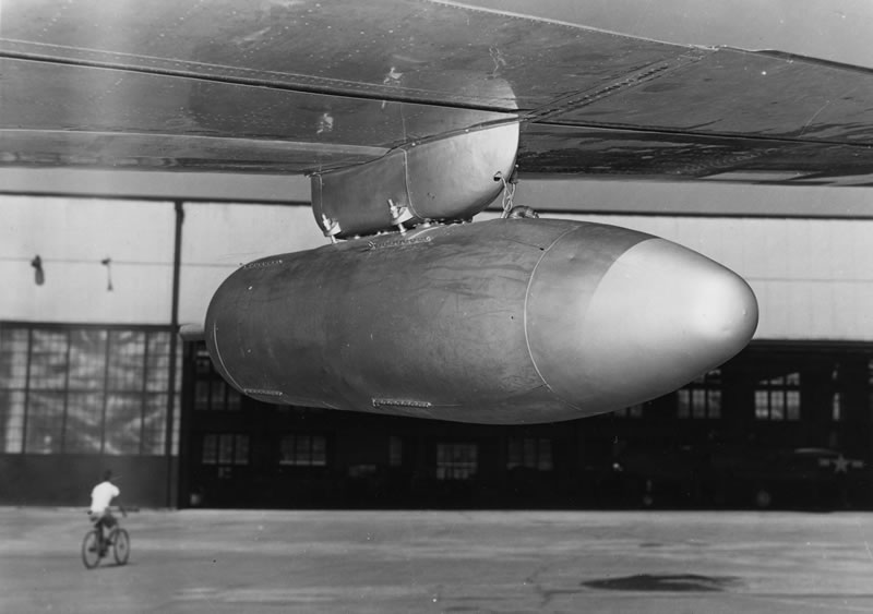
A package gun was shown mounted beneath the right wing; a second image showing the front of the package would have been useful, but none was included in the folder. Nothing indicated whether the aircraft was designed to carry two package guns or just the one shown.
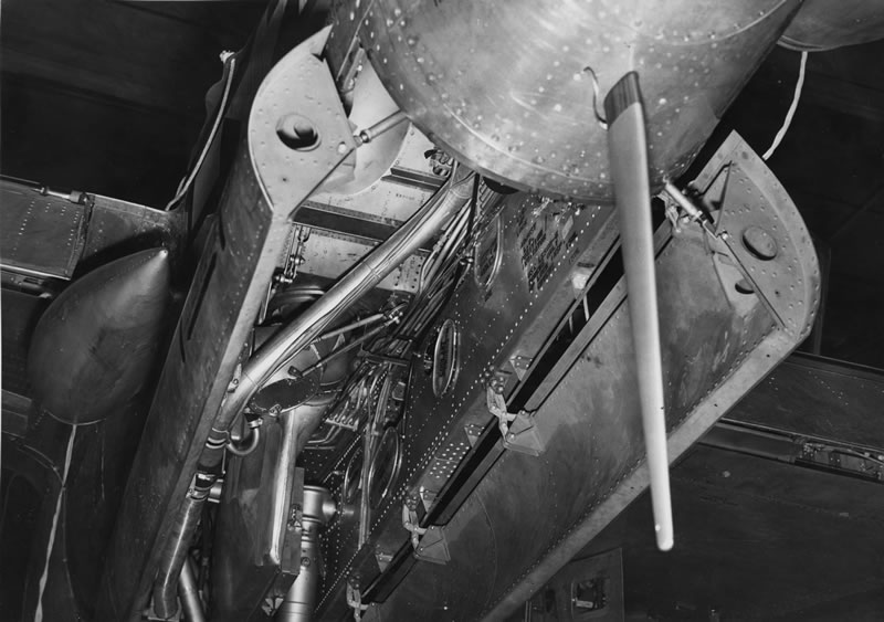
The AN-104 radio antenna, normally located forward of the nose gear, was relocated behind the left main gear well. The image of the antenna provides a pretty good view of the unpainted well.
Text and Images Copyright ©
2013 by Dana Bell
Page Created 13 February, 2013
Last Updated
13 February, 2013
Back to Reference Library |
Home |
What's New |
Features |
Gallery |
Reviews |
Reference |
Forum |
Search