|
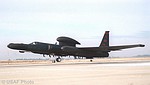 |
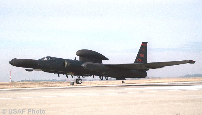
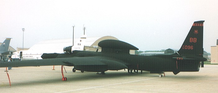
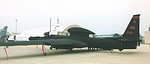
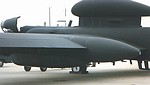
01 - Ultimate "Dragon Lady" -- 80-1081
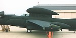
While being a different aircraft from the one I saw at Andrews AFB in 1996, this aircraft represents the full package of all the major sensors carried by the U-2. The nose has the ASARS II update, the super pods and lower fuselage have Senior Glass (combined Senior Spear and Ruby), and the Senior Span/Spur satellite up-link pod is present on top.
|
|
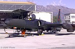 |
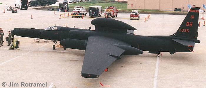
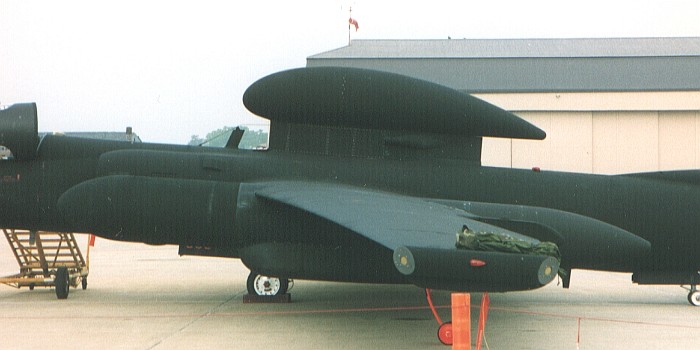
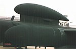
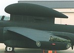
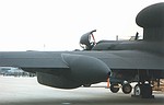
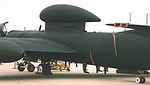
02 - "Dragon Lady" at Rest -- 80-1082
One serial number away from the aircraft in the previous picture, this aircraft is outfitted the same, minus the Senior Span/Spur dorsal pod. Note the varying colors of the nose and other dielectric panels as compared to the overall aircraft color. Specifications call for the entire aircraft to be black. It is amazing how many shades of black exist. Note also the color of the engine intake duct.
|
|
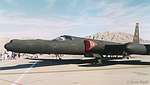 |
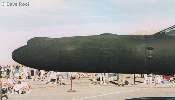
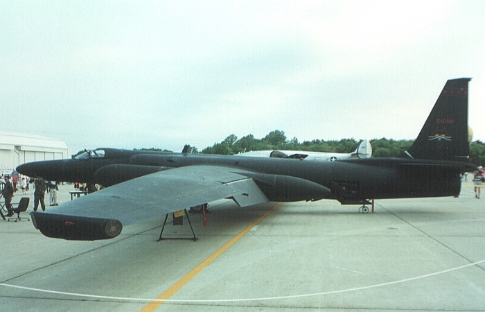
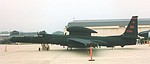
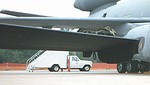
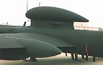
03 - "Dragon Lady" at Rest -- 80-1073
This is the aircraft that Dave Roof saw at the 50th anniversary of the US Air Force, Nellis AFB. Of special note is that the ASARS nose is not much different in color from the rest of the airframe. Typically, the ASARS nose tends to be much darker than the rest of the airframe.
|
|
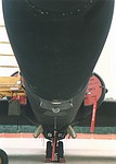 |
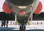
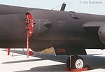
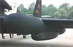
04 - Nose Underside
This is the underside of the nose. The glass dome is the eye-piece for the drift scope in the cockpit. Note the darker color of the ASARS II nose and the lighter color of the flush antenna panels further back on the fuselage. Officially, everything is painted black. The lighter and darker black areas are attributable mostly to varying sheen and weathering of the affected areas.
|
|
 |
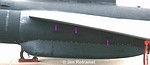
05 - Nose Underside
This is different aircraft from the previous picture. Notable in this picture is that most of the same panels stand out as being different colors from the rest of the airframe.
|
|
 |
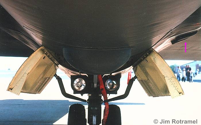
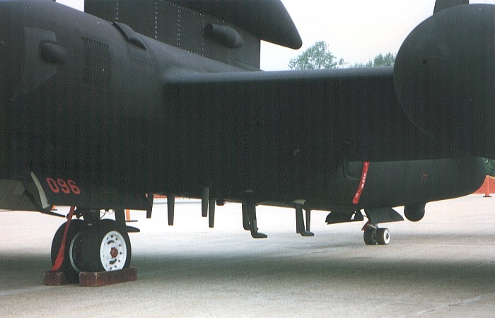
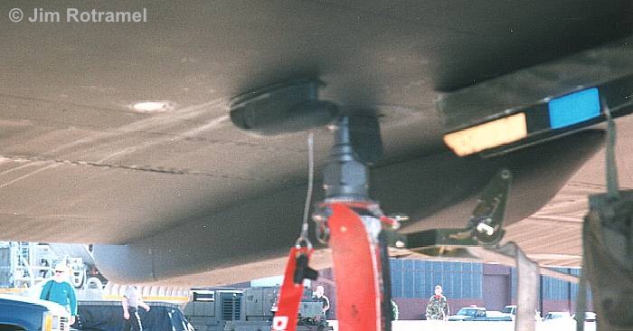
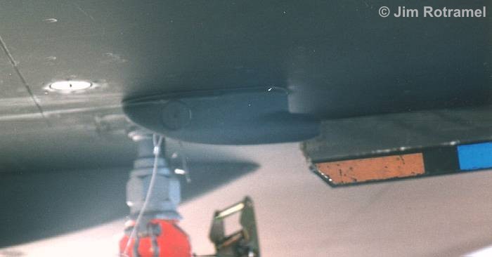
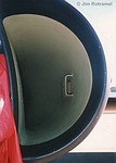
06 - Main Wheel Well Doors
This view shows the alignment and colors of the main wheel well doors. Note the colors of the various items. The door interiors are a light greenish-yellow and the landing gear strut (with the door actuators) is a dark metallic color. The bulbous antenna in front of the wheel well is the forward data-link antenna. A second data-link antenna exists in a different shaped bulge under the tail. Also note on the right side of the picture some vents that are only present on the left side of the aircraft.
|
|
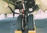 |
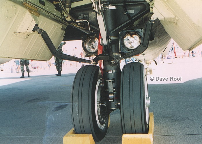
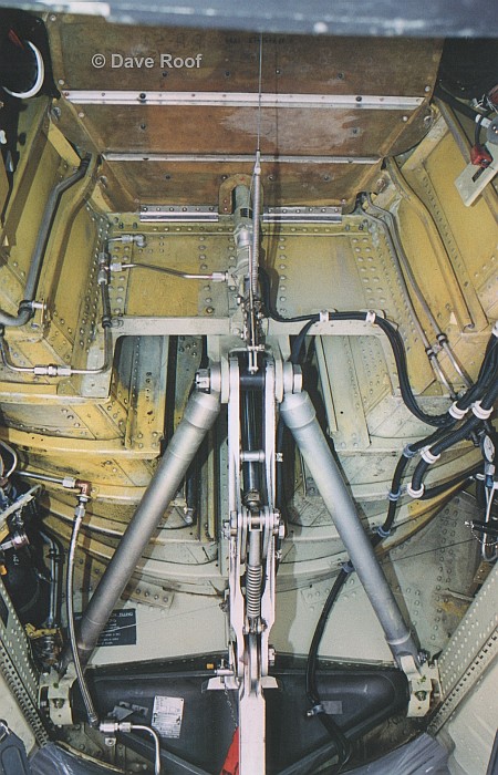
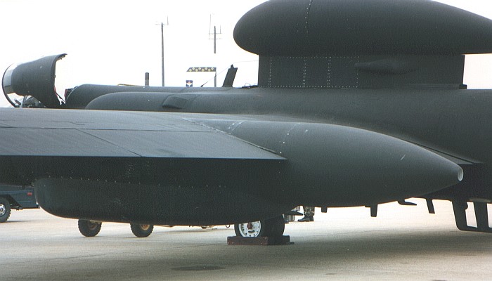
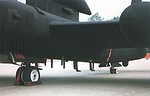
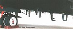
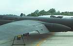
07 - Main Landing Gear -- Looking Aft
This is a close-up of the main landing gear, seen from the front. The general arrangement of all the retraction arms is important to note. Points of interest for the colors in this area are the metallic black strut, the light colored retraction arm, and the light yellow/green wheel well door interiors.
|
|
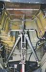 |
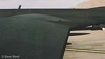
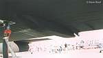
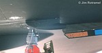
08 - Main Wheel Bay -- Looking Aft
This view of the space into which the main landing retracts shows without a doubt that there is no "well" for the main landing gear. The ribbed upper structure is the outside of the engine intake ducting. There are no side walls, with the space being open into the rest of the airframe on either side of the opening. Color notes are important here. The inner area appears to have been chromate yellow at one time. Later, the lower areas were over-painted with a creamy light yellow/green color, but the rest of the area remained chromate yellow.
|
|
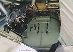 |
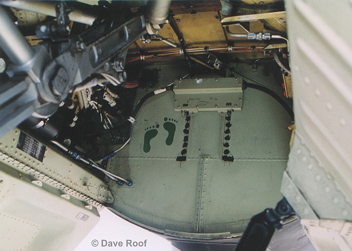
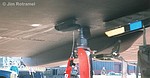
09 - Main Wheel Bay -- Looking Forward
This is the forward end of the main landing gear bay. Note the front bulkhead is painted in the light yellow/green color and has been zapped with a pair of footprints.
|
|
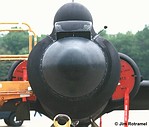 |
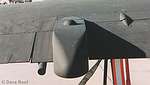
10 - ASARS II Nose
This head-on view shows the cross section and some details of the ASARS II nose. Note the small actuator oleo inside the upper cooling intake. The bulbous upper shape is the top of the Senior Span/Spur dorsal antenna pod.
|
|
 |
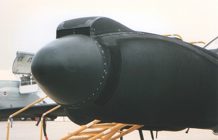
11 - ASARS II Nose
This view shows the details of the forward section on the ASARS II nose. Note the shine to the very front section and the extremely flat finish on the rest of the nose. While there is no apparent panel line to mark the location, the pattern of flat and not-so-flat paint on the nose side indicates the location of the dielectric panels on the nose.
|
|
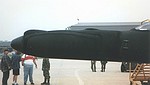 |
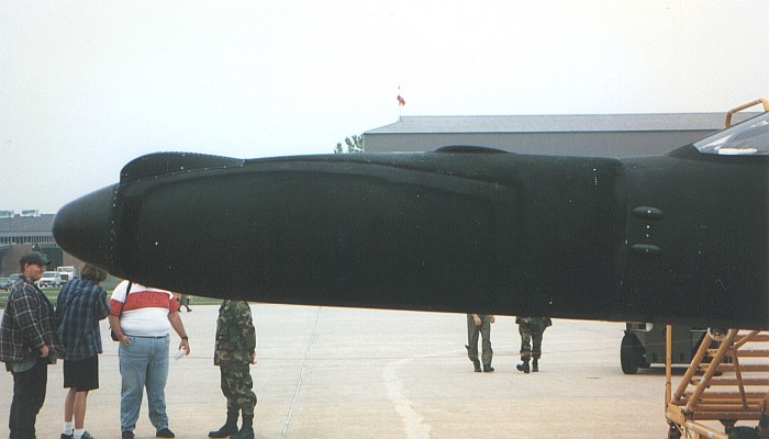
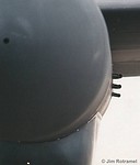
12 - ASARS II Nose
This is a left side overview of the ASARS II nose. Note the darker color of the nose as compared to the rest of the aircraft. Note also the two small blisters on the fuselage side just behind the ASARS II nose. These blisters are mirror imaged on the right side of the nose and only pertain to ASARS II equipped aircraft.
|
|
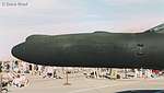 |
13 - ASARS II Nose
This is pretty much the same view as the last picture, only on a different aircraft in different lighting. The outline of the dielectric panels in the nose are not as easily seen in this picture because the nose colors are more uniform.
|
|
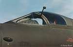 |
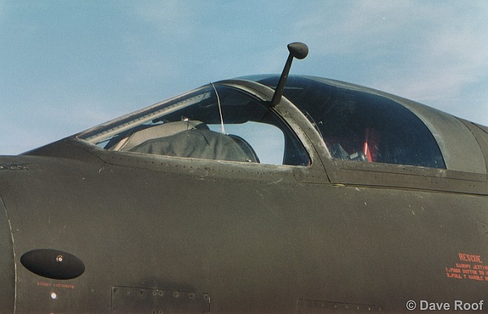
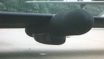
14 - Left Canopy, Closed
This view shows the closed canopy from the left side. Note the color/details of the forward instrument hood. The thread-looking thing draped down the middle of the windshield quarter panel is the yaw string. Attached to the top of the canopy, this string allows the pilot to accurately gauge the crab angle (yaw) of the aircraft in flight.
|
|
 |
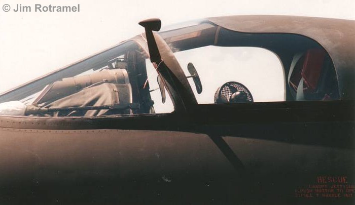
15 - Left Canopy, Closed
This view shows the closed canopy from the left side. Details to note are the cockpit fan, rearview mirrors (inside and outside), and the color/details of the forward instrument hood. The yaw string is draped over the external mirror post in this picture.
|
|
 |
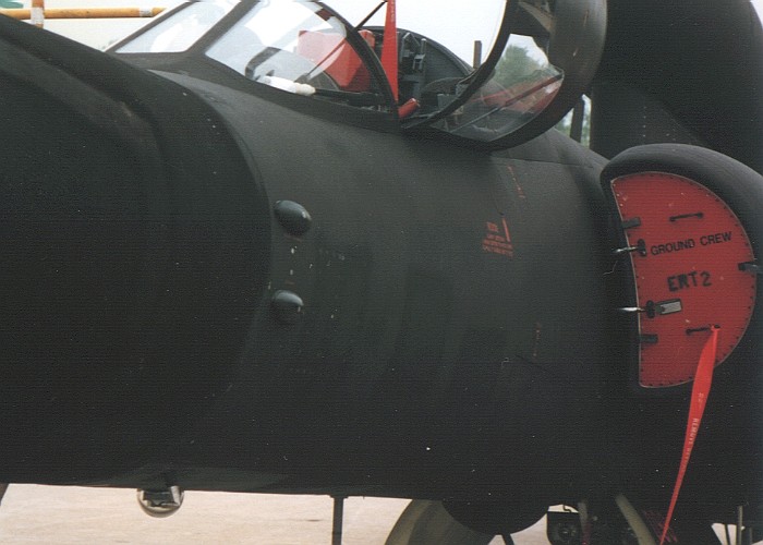
16 - Left Forward Fuselage
|
|
 |
17 - Left Forward Fuselage
A closer view of the forward fuselage side. Note the drift scope dome under the fuselage and behind the lower left pitot. This view provides better details on the two blisters just behind the joint line for the ASARS II nose. Two more blisters are mirror-imaged in the same location on the right side of the nose.
|
|
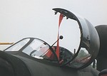 |
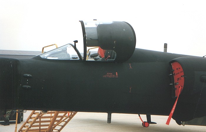
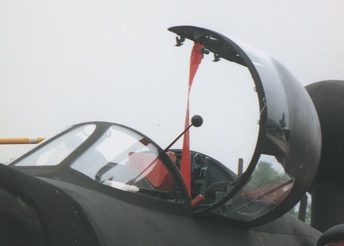
18 - Cockpit
This is a close-up of the cockpit from the left side with the canopy open. Note the external rearview mirror mounted to the left side of the windscreen. Note also the latching points along the side of the canopy. Almost invisible along the forward canopy framing is the yaw string. You can just make out the attachment point of the yaw string on the middle of the forward canopy framing.
|
|
 |
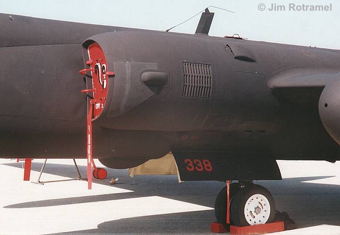
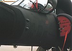
19 - Left Engine Intake Overview
This view shows the left engine intake and the areas around it. Note the dielectric panel and ECM blister on the intake side. Also note the oil cooler exhaust grill behind the ECM blister. The specific lighting of this picture makes the oil cooler grill very noticeable. In most pictures, the grill is almost invisible.
|
|
 |
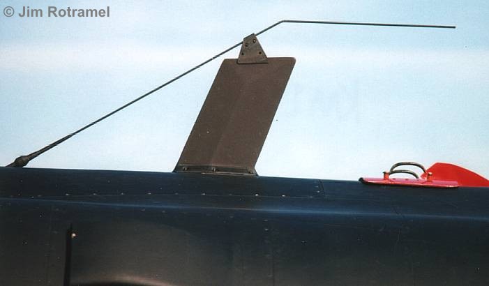
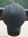
20 - UHF/ADF Antenna
The large blade antenna is the UHF radio antenna. The thin whip as an ADF antenna. The whip was originally straight. The bend in the upper portion of the whip antenna was introduced to provide clearance for the Senior Span/Spur dorsal pod. Most U-2 aircraft seem to now use the bent whip, even if they are not capable of carrying the Senior Span/Spur dorsal pod.
|
|
 |
21 - Left Engine Intake Ducting
This is the inside of the left engine intake. The major thing to note here is the color of the ducting. This is the color of most all the inner portions of the U-2 airframe. Depending on the lighting, this color is anything from a pale yellow to a light lime green. I have not found a definitive answer to what the exact color is, but some sources claim the color is either a nondescript mixture of Gloss White and Chromate Yellow/Green or a coating of Gloss White applied over Chromate Yellow/Green. The intake scoop on the outer duct wall is for the oil cooler.
|
|
 |
22 - Middle Fuselage
This is the center left fuselage area where the wing is attached. Obvious in this picture is a good portion of the antenna farm found on the belly of the aircraft. Also note the oil cooler exhaust louver on the fuselage side ahead of the wing and the flat intake scoop just above and behind the louver. This flat scoop is only on the left side. Finally, note the wheels are white while the landing gear strut appears to be a dark metallic shade.
|
|
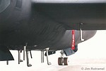 |
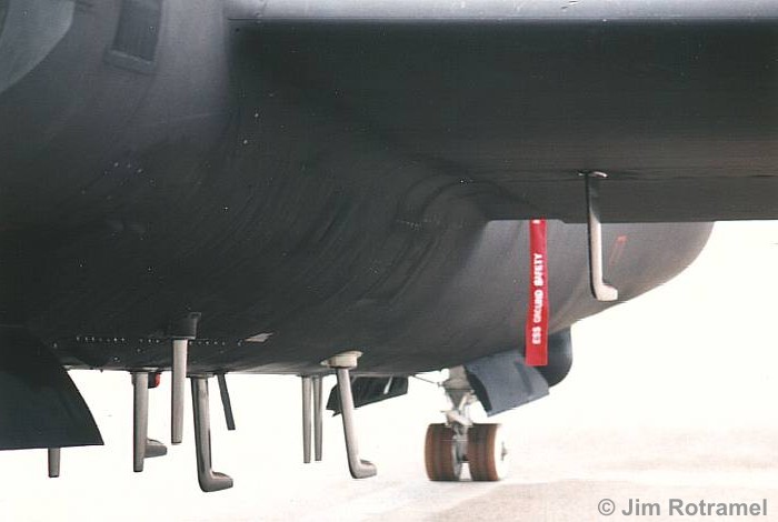
23 - Senior Spear Antenna Farm
This is a closer view of the antenna farm that is part of the Senior Spear installation. Note that the blade antennae are all glossy finished. Note also that one of the hockey stick shaped blade antennae is mounted to the lower wing. This installation location is mirrored on the underside of the right wing, also.
|
|
 |
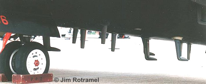
24 - Senior Spear Antenna Farm
This is another close-up view of the belly antenna farm and main landing gear. Note the red hubcap on the main wheel.
|
|
 |
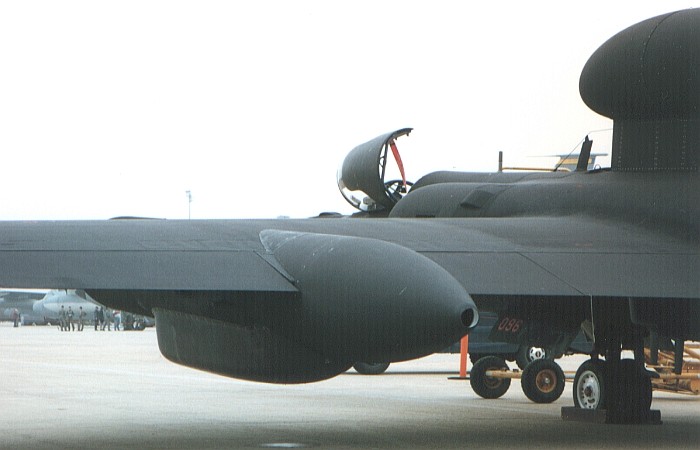
25 - Left Super Pod
This view shows the inside of the left super pod. The canoe fairing under the pod is part of the Senior Spear installation.
|
|
 |
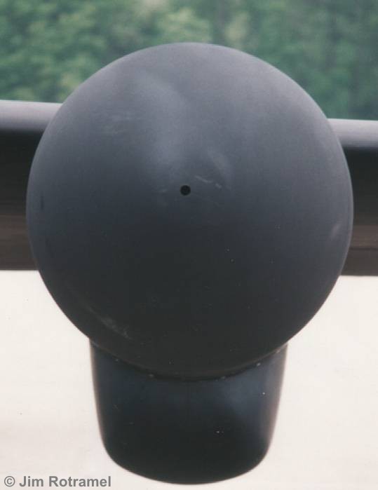
26 - Left Super Pod
This is a straight, head-on view of the left super pod. Note the vent hole in the forward tip of the super pod.
|
|
 |
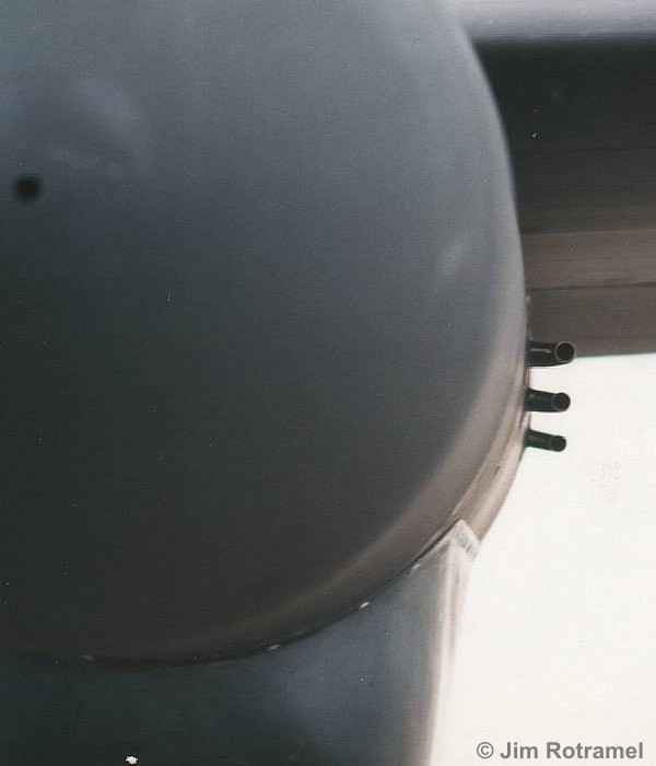
27 - Left Super Pod Intake Scoops
This view clearly shows the elusive intake scoops found on the left super pod side. These scoops are small and remain mostly hidden in the shadow of the wing in most photographs. They provide cooling air to the Senior Spear avionics housed in the super pod and canoe fairing.
|
|
 |
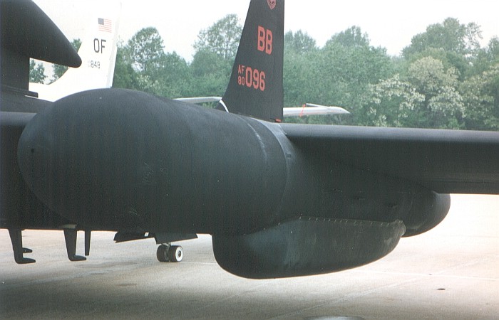
28 - Left Super Pod
This view shows the outside of the left super pod. Note the darker, flatter finish on the super pod forward section as opposed to the rest of the aircraft. Note also the orientation of the cooling scoops on the super pod side. The leading one faces straight forward while the middle and rear ones are canted downward slightly.
|
|
 |
29 - Left Super Pod Side
This view shows another angle on the elusive intake scoops found on the left super pod side. The pink arrows are added to better highlight the scoop positions. Also of note in this picture is the shape of the canoe fairing under the super pod.
|
|
 |
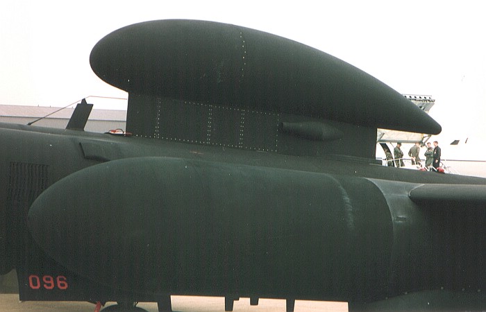
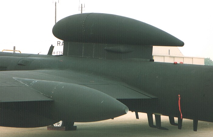
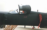
30 - Senior Span/Spur Dorsal Antenna
The most striking and noticeable change to the basic U-2S aircraft in recent years has been the addition of Senior Span/Spur and the large dorsal antenna pod. The pod holds an up-link antenna for satellite communication that allows the aircraft to beam its data back to any location on Earth in near to real time. Note the bent whip antenna in front of the pod. This whip was originally straight on U-2 aircraft, but it was modified to gain clearance for the Senior Span/Spur dorsal antenna.
|
|
 |
31 - Left Side Overview
|
|
 |
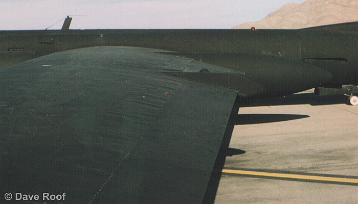
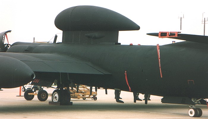
32 - Left Center Fuselage Overview
This overview provides information on the Senior Span/Spur dorsal pod location relative to the wing root on the aircraft.
|
|
 |
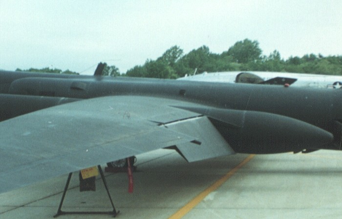
33 - Left Wing
Besides the view of the dorsal antenna pod, this picture provides an overview of the left wing top and details of the left wingtip pod.
|
|
 |
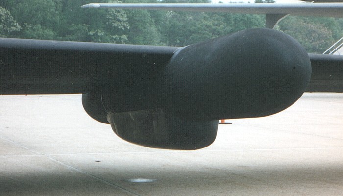
34 - Left Wingtip
This view shows the inside of the left wingtip. The lighting was not the best, but you can see the wingtip skid that protects the wingtip during landings. The wingtip pod is mounted onto the outside surface of the wingtip skid. The odd shapes hanging off the tailing edge of the outboard wing are portions of the crew jacket laying on top of the wing.
|
|
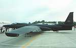 |
35 - U-2R 80-1098
This is a left quartering view of a U-2R I saw at an earlier Andrews AFB air show. I wish I had taken more pictures of this one as the flaps were down...
|
|
 |
36 - Left Rear Quartering Overview
|
|
 |
37 - Left Outboard Wing Flap
This is a closer view of the lowered wing flaps. Note the angle of the flaps (which is full deflection) and the light colored strip that becomes visible when the flaps are lowered. Different aircraft and time periods show different colors for this light colored strip. Some show what appears to be natural (unpainted) metal. Others appear to be an off white or very light gray color.
|
|
 |
38 - Left Wing Trailing Edge
|
|
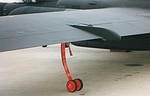 |
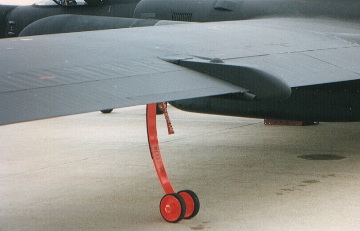
39 - GPS Antenna and Left Pogo Leg
The orange wheeled leg under the wing is referred to as a pogo and is dropped off as the aircraft takes off. Note its color is orange, not red. The GPS antenna is the tiny dome located on top of a squared extension that protrudes between the wing flaps and aileron.
|
|
 |
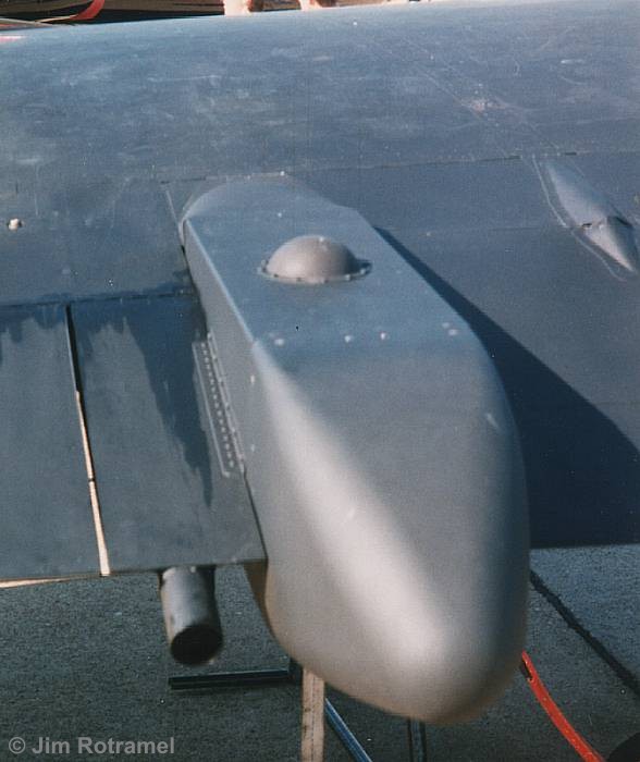
40 - GPS Antenna Fairing
This large fairing on the left wing is a relatively new addition to the U-2 fleet. The actual GPS antenna is the small dome on top of the fairing. The forward portion of the fairing is mounted on to top the outboard end of the roll-control spoiler. The pipe emerging from between the fairing and the aileron is a fuel dump.
|
|
 |
41 - GPS Antenna Fairing
This view from directly aft on the antenna fairing provides more information of the relative location of the fairing between the wing flaps and the aileron.
|
|
 |
42 - GPS Antenna Fairing
This is the fairing under the wing. Note the length of the fairing which is much longer than the corresponding fairing on top of the wing. Note also the details of the fuel dump pipe and aileron trim tab actuator.
|
|
 |
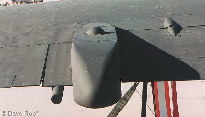
43 - Wing Fuel Tank Pressurization Scoop
The scoop on the lower wing, just inboard of the attachment point for the pogo leg is a scoop to provide positive pressure inside the wing fuel tanks. The blue and yellow marked item on the right side of the picture is the upper portion of a wing prop.
|
|
 |
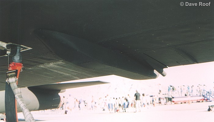
44 - Wing Fuel Tank Pressurization Scoop
This is a second angle on the same scoop that was seen in the previous picture. Note the orientation of the scoop with the trailing edge mostly even with the attachment point for the pogo leg.
|
|
 |
45 - Left Super Pod
This view shows the outside of the left super pod. Note the vent hole in the tip of the rear super pod cone and that the color inside the vent hole is white.
|
|
 |
46 - Left Super Pod
This view shows the rear of the left super pod. Note how the super pod fairs into the wing.
|
|
 |
47 - Senior Span/Spur Dorsal Antenna
This rear quartering view of the Senior Span/Spur dorsal antenna pod provides more information on the location of the pod, relative to the wing. Also visible is a portion of the antenna farm on the bottom of the aircraft and the double anti-collision beacon lights on the upper fuselage.
|
|
 |
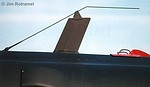
48 - Center/Rear Fuselage Overview
Dominating the view is the dorsal antenna pod for Senior Span/Spur. The red item attached onto the horizontal tail tip is a control lock so the wind does not move the flight controls.
|
 Home |
What's New |
Features |
Gallery |
Reviews |
Reference |
Forum |
Search
Home |
What's New |
Features |
Gallery |
Reviews |
Reference |
Forum |
Search