|

HyperScale is proudly supported by
Squadron.com
With the recent re-release by Italeri of the
ESCI 1/48 S-3 Viking, and a surge in availability of aftermarket
parts and decals for the S-3, it seems as though the modeling
community’s interest in the Viking has recently reached a new peak.
This article is the first in a series that will cover the evolution
of the S-3A and B from a modeler’s perspective, and will focus on
building an accurate S-3A or B (up through the “ASW deconfiguration”
modifications) from the ESCI kit. Future articles will cover S-3
weapons and external stores, special projects Vikings (including
OUTLAW Viking, Gray Wolf, ODIN, and the Sensor Systems Upgrade),
Viking cockpits, ejection seats, and flight gear, and upgrades that
have recently reached the fleet, such as the Communications
Improvement Program and the Maverick Plus weapons system upgrade.
Although both Airfix and Hasegawa have produced
1/72 scale S-3s that are good starting points for a small-scale
Viking, this article is tailored to the ESCI 1/48 Viking kit. All
dimensions referenced are for 1/48 scale and should be reduced
appropriately if you are working with the Airfix or Hasegawa kits.
All three kits are accurate representations of a production S-3A
right out of the box, and most of the visible changes associated
with the S-3B upgrade and subsequent modifications are well within
the capabilities of the average modeler.
The single best published reference on the S-3
is World Air Power Journal Vol 34; it provides an excellent
development and operational history of the S-3 up to the late 1990s
and includes a great selection of photos. It is highly recommended
for the modeler.
The changes outlined below are arranged in
rough chronological order as they appeared on the airframe. A total
of 187 S-3As were delivered from Lockheed to the U.S. Navy from
1972-1978. These aircraft were produced with only one mission
requirement: protect carrier battle groups from the Soviet submarine
threat. With the rapid expansion and modernization of the Soviet
surface navy in the 1980s, the Viking’s role expanded to include
over-the-horizon targeting, reconnaissance, and anti-ship strike.
The S-3B was developed to meet these new mission requirements. S-3B
upgrades included enhanced acoustic processors, an upgraded Inverse
Synthetic Aperture Radar capable of imaging ships from long ranges,
a new Electronic Support Measures (ESM) system tailored to detect
and identify the latest Soviet naval radar systems, self-protection
chaff and flare dispensers, and the AGM-84 Harpoon antiship cruise
missile. All production S-3Bs were remanufactured from existing
S-3A airframes between 1989 and 1992. The collapse of the Soviet
Union and the lessons learned from the Gulf War in 1991 led to the
initiation of numerous additional avionics and weapons system
upgrades that are still ongoing. In 1998, due to a drastic shift in
mission focus away from antisubmarine warfare, the Navy elected to
remove the Viking’s acoustic processors, sonobuoy reference system,
and magnetic anomaly detector (MAD). This modification program
became known as the “ASW deconfiguration” program – somewhat of a
misnomer as the Viking retains the most advanced periscope detection
radar in service today and is still capable of delivering ASW
torpedos. All Vikings were brought to this configuration in
1999-2000
|
Corrections and Modifications |
Airframe Corrections for any S-3A or B:
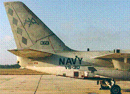
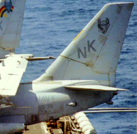
- Add low-intensity strip lights on forward
fuselage, aft fuselage, and vertical stabilizer (strip lights were
added to all S-3’s in the early 1980s).
As shown in the photos below, the pattern is two connected strip
lights under the canopy, three connected strip lights on the aft
fuselage, and two sets of two connected strip lights above a
single strip light following the first panel line back from the
leading edge of the vertical stabilizer.
Click the thumbnails
below to view larger images:
Baseline S-3B updates:
- ESM Antennas: The 8 ESM antennas at
the fore and aft ends of the wingtip ESM pods need to be modified
to correctly represent the S-3B’s ALR-76 ESM antennas. Sand the
little antenna bumps of each pod (JUST the 4 small round bumps,
NOT the wingtip position lights) and either use the ALR-76
antennas provided in the Eduard photoetch set or make your own by
cutting some .010 sheet plastic into squares to match the facets
on the antenna pods. Use a dull knife – you want a raised ridge
around the edge of the new antenna. A small dome rivet or a drop
of white glue should be placed in the center of each new antenna.
S-3A ALR-47 ESM Antennas (left wing, spread)
S-3B ALR-76 Antennas (right wing, folded)
- ECM dispensers: The S-3B is equipped
with the ALE-39 ECM system and has 3 expendable payload buckets –
one on each side of the aft fuselage just forward and below the
lower forward corner of the left and right aft avionics bay doors
and one on the belly just forward of the sonobuoy chutes (see the
belly photo of the S-3B in the “ASW deconfiguration”
section, below). The buckets have 30 chutes arranged 6vertical by
5 horizontal. ALE-39 buckets can be sourced from the Eduard S-3B
photoetch (although it only includes two) or the out-of-production
Teknics photoetch set of ECM dispensers and formation lights. The
modeler on a schedule can simply scab on some appropriately-sized
(1/4” vertical by 7/32” horizontal) rectangles of sheet plastic at
each dispenser location to represent the blank-off plates that are
installed when the aircraft is not actually carrying chaff or
flares.
Right side ALE-39 blankoff plate
Left side ALE-39 dispenser with
(just below the “30”in VS-30).
10 flares (silver) and 20 chaff
Note position relative to fuel rounds
(blue) loaded.
filler cap.
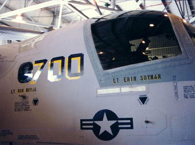
- GPS antenna: Added under a separate
program, the GPS antenna was installed on fleet S-3B aircraft from
1996-1999. The GPS antenna is a small black “brick” antenna on
the center canopy frame above and behind the refueling probe
door. In 1/48 scale, the GPS brick antenna can be simulated with
a 1/8” x 3/16”rectangle of .040 sheet plastic with the leading
edge located ½” aft of the aft edge of the refueling probe door.
The antenna should be centered on a backing plate made of .010
sheet with the outer edges beveled; the backing plate should be
the same dimensions as the kit-supplied refueling probe door.

GPS antenna on S-3B center canopy frame.
Refueling probe door can be seen at extreme right of the photo.
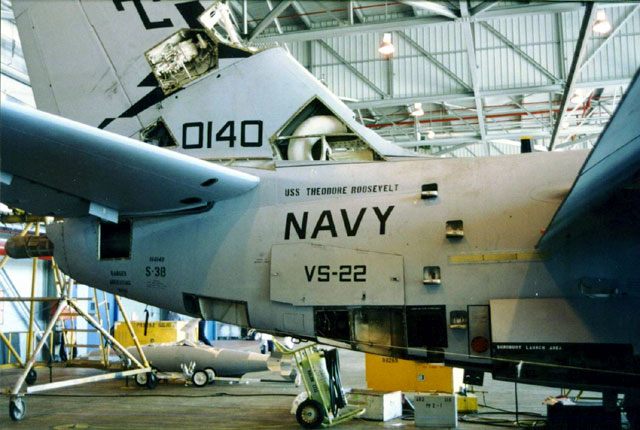
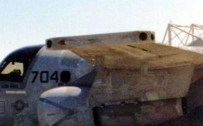
AFC-284 “ASW Deconfiguration”
Modifications:
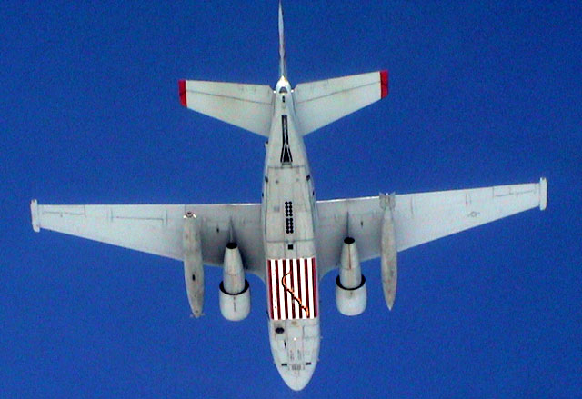
VS-38 CAG Viking showingAFC-284 sonobuoy
chute arrangement, belly ALE-39 ECM dispenser on centerline forward
of sonobuoy chutes, and MAD boom blank-off plate (just visible
inside extreme tail)
- MAD boom: Leave it out. The MAD
boom is removed and the hole in the tail is blanked off with a
flat plate from the inside. From any aspect except looking
straight at the tail of the aircraft from behind, it looks like
the boom just fell out.
- Antenna removal: Remove all antennas
from the lower wings and gear doors. Remove the raked blade
antenna from the top center of the fuselage – it represents a
LORAN/Omega antenna only carried on US-3s. Also remove the
forward blade antenna on the aircraft centerline just aft of the
canopy. There is a blade antenna offset slightly to the left of
centerline aft of the canopy; this should be retained. The 3
centerline blade antennas on the belly should be retained, as
should the aft-most blade antenna on the upper fuselage. Check
references for your particular aircraft for the antennas mounted
beside the starboard nose gear door. Antenna configuration can
vary if certain “add-on” equipment is carried while deployed.
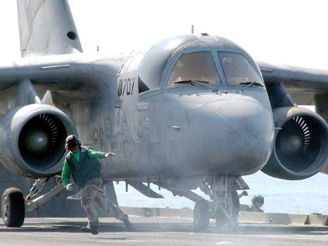
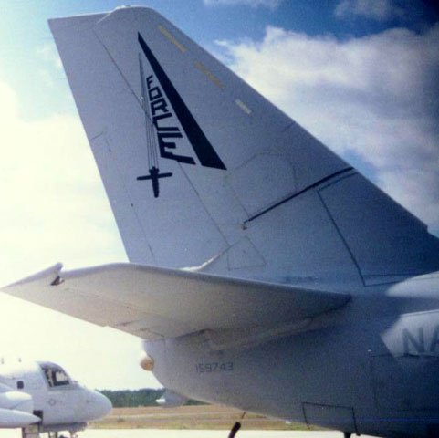
VS-21 Viking on the cat showing AFC-284 fuselage blade antenna
configuration
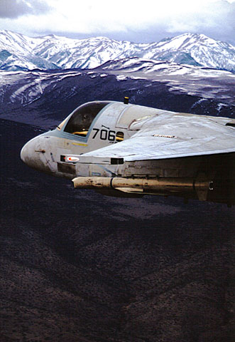
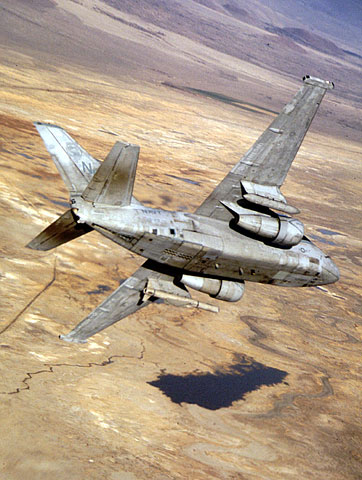
VS-29 Viking over the Sierra Nevada
showing offset upper forward blade antenna
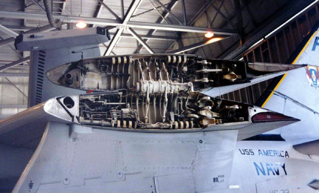
- Sonobuoy launch area: AFC-284
reduces the number of sonobuoy chutes from 60 to 16. Count 8
pairs of sonobuoy chutes starting at the extreme front of the
sonobuoy launch area. Keep these and cover the rest with sheet
plastic and fair it into the existing surface.
As you can see, the external changes
required to update your Viking are relatively minor. Check
references for the particular aircraft you are building, as antenna
configurations can differ subtly in detail. The next article will
focus on weapons and external stores.
Text and Images
Copyright © 2003 by LCDR Bill Suggs
Page Created 10 March, 2003
Last updated
10 March 2003
Back to HyperScale Main
Page
|  Home |
What's New |
Features |
Gallery |
Reviews |
Reference |
Forum |
Search
Home |
What's New |
Features |
Gallery |
Reviews |
Reference |
Forum |
Search